Saturday, April 30, 2011

24" Radiator Installed

Lauren had work today and I wasn't able to play softball tonight (due to the stitches in my chin) even though tonight was the mens league playoffs; the Mustang benefited. With my new radiator in hand, I was excited to get to work installing it. I referred to Mustang Steve's picture of where he recommends that the radiator support be cut although I detoured from it a little. I had an idea to cut the support and then to fold it over 180 degrees in order to use the folded metal as the mounting point for the new radiator.

66 Mustang Radiator Support Marked for Modification

I made a horizontal cut along the top and the bottom of the support and then cut made a vertical cut on each side of the opening while leaving some of the support to fold towards the fenders. There are two vertical marks because I had marked it to leave some extra and then realized that once I folded the flap over on the passenger/battery side  would hit the '69 battery tray. I re-marked it about 1 1/8" from Mustang Steve's line. I realized after the fact that I should have cut a larger flap on the driver's side because the radiator doesn't sit in the car symmetrically and I came up short on the bottom mount of the driver's side. The radiator will do fine with three bolts holding it though and doesn't require the fourth.

'66 Mustang Support Cut to Fit 24" Radiator


Once the radiator was bolted in, it looked like it was made for the car. It was a tight fit, but that is what made it seem like it was designed for this car.


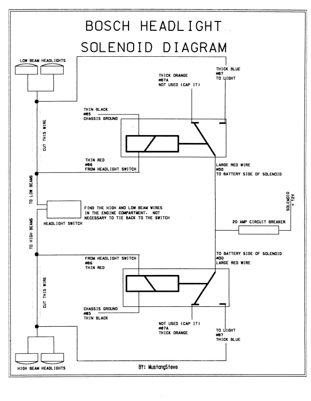
I actually started the day by looking up the firing order for my 302 and then installing the spark plug wires. The firing order on early (non 80's Mustangs) is 1-5-4-2-6-3-7-8. I laid out the wires in order from longest to shortest to make sure I didn't put a long wire where a short one was needed.

Early 289 and 302 Firing Order

The plug wires looked fine even though they weren't black like the ones I ordered. The coil wire would not stay on the coil for some reason so I pushed it through the boot a little further and that seemed to help it stay on the coil.

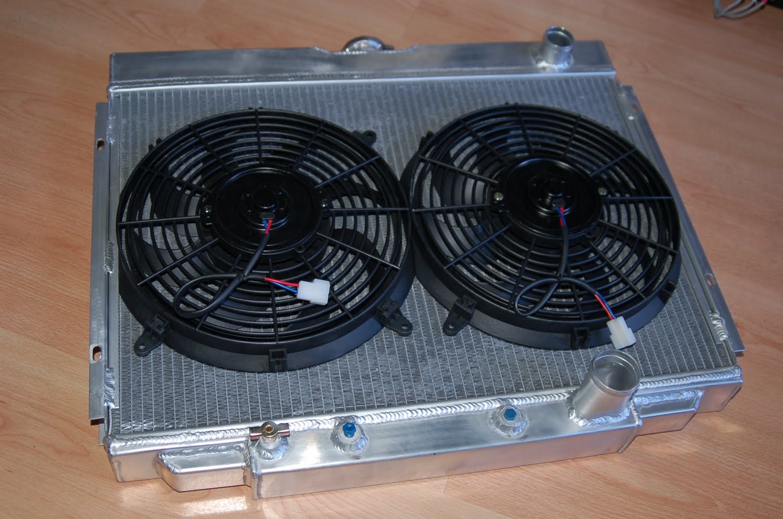
Once I had the radiator opening cut, painted and the radiator bolted in the car, I was able to cut the radiator hoses to fit. I cut about 4" off the top hose and about 1 1/2" from the lower hose. I also installed the temperature probe for the electric fan relay.

Thermostat Housing with Extra Water Jacket
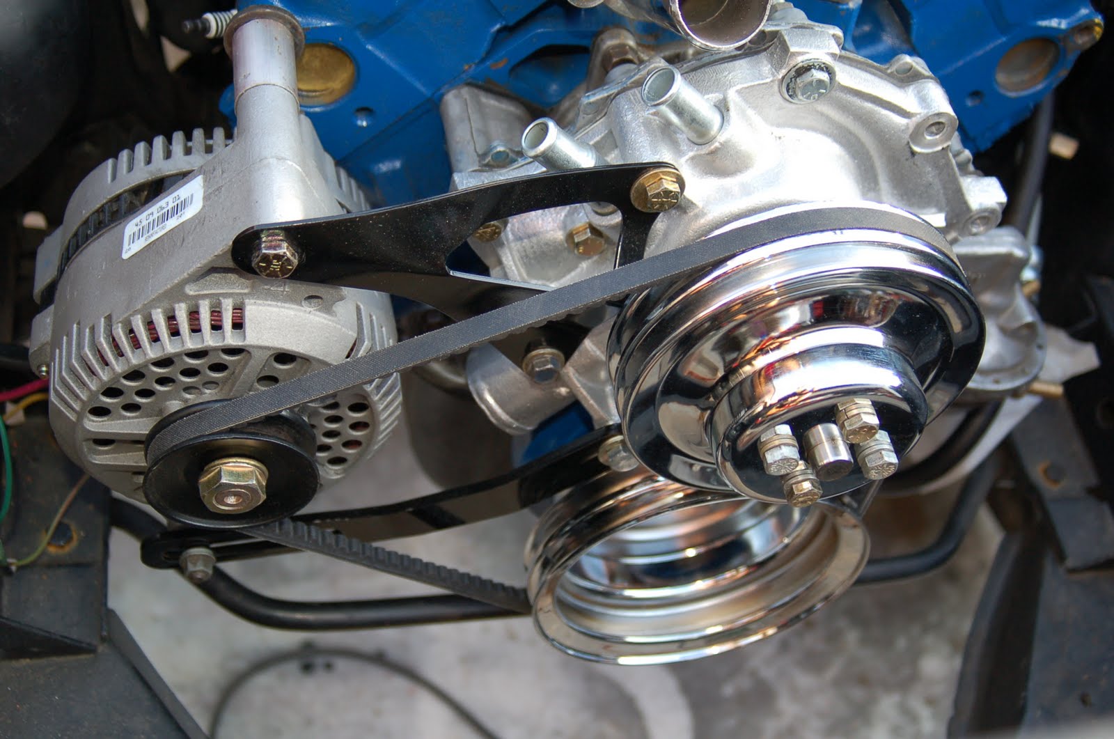
The relay switch for the electric fans is able to be set to turn on between 150-240 degrees using only a screwdriver. I mounted it below the starter solenoid since it is more convenient to have it near the solenoid and the battery with wires needing to go to both areas. The relay also allows for a manual override switch to be installed. Of course I am choosing to run the manual override in case I am driving and the fuse blows while I'm on the freeway or sitting in gridlock traffic. I haven't yet hooked up the switch inside the car, nor do I know exactly where I'm going to put it, but there is a green wire running through the engine loom into the firewall with a piece of masking tape that says "Elec Fan Manual Switch." You can see the green wire below coming off of the relay switch.

Left: Temp Relay Switch, Right: 3G alternator
From the front, the radiator looks huge for this year car. If you're used to seeing the 1965-66 Mustangs, then you know how small the radiators usually look. I'll be mounting the hood latch soon which will sit in front of the radiator. The 1969 Mustang/Cougar battery tray that I modified to fit works perfectly with this radiator. The mounting bracket of the radiator almost touches the battery tray.


Thursday, April 28, 2011

New 24" 3-Row Aluminum Radiator


After a lot of searching I found an awesome deal on a Champion 24" 3-row aluminum radiator with dual electric fans (2800 CFM combined) on Ebay from a seller in Orange (Classic Radiators.) He buys in bulk from the factory in Lake Elsinore and sells them on Ebay, but I bought mine  in person so that I could avoid spending $40 on shipping.

24" Mustang Radiator with Dual 12" Electric Fans

In order to get maximum air flow through the radiator support, I'll be cutting out about 2.5" on each side of the support. It's not completely necessary, but it will help with cooling. I will have to fabricate mounting brackets since the radiator is wider than the location to place mounts. I will also need to fabricate mounts for the fans to mount onto the radiator since I don't want to run plastic strips through the center of the radiator. I'll probably be able to put something together with some adjustable metal straps. The water temperature sensor with adjustable relay came in the mail yesterday afternoon as I mentioned in my previous blog. I picked it up on Ebay for $51.95 with shipping.

Adjustable Water Temp Relay Kit for Electric Fan

Wednesday, April 27, 2011

Brighter Headlights

Following the directions of both Mustang Steve and James W. I ran power directly from the battery side of the starter solenoid and hooked it up to a relay that will give direct power to my headlights once triggered by the headlight switch. When I looked at the numbers on the relay, they didn't correspond with the colors listed on Mustang Steve's diagram (i.e. his diagram shows two red wires per harness and mine only had one.) I made sure to match up the numbers on the relay with the correct color wires. We'll know more once the car has a battery in it that will allow us to test it. The green-black wire from the firewall is for the high beams and the red-black wire is for the low beams. You can see where I spliced into the harness below:


Mustang Headlight Wires

I made sure to run 12 gauge wire from the relay to both headlights for safety. Based on my limited availability of wire colors, I used plain red for the low beams (red-black) and blue for the high beams (green-black.) I tried to run the replacement wires through the loom to keep everything as neat as possible. Once I laid out all of the new wire, I was able to hook it up to my new headlight harnesses that I purchased on Amazon.

New Headlight Harness

Once all the wires were spliced in and taped, I wrapped them with the same loom casing that I used on the wires coming off of the firewall the other day. I spliced in the inline fuse right above the battery rather than near the relays and wire harness in order to keep it less cluttered. Instead of running the suggested 10 gauge main wire from the battery, I ran 8 gauge wire (heavier) mainly since we didn't have much 10 gauge wire laying around. The red wire you see below is the main wire from the positive solenoid post to the relays.

Relays Spliced into Existing Harness

Once I had finished with the wiring, I re-installed the overflow tank that had come with the car. I simply mounted it over the wire loom near the power steering pump.


Overflow Tank Installed

When I arrived home and checked the mail I found that I had received both the water temperature sensor with relay for the electric fans as well as the spark plug wires. The plug wires were supposed to be black but instead they sent me blue which is a bummer because it doesn't match the motor nor does it match the distributor cap so I'll have a third shade of blue under the hood. I also recently received the front/rear valances and the gas tank kit which I'll install as I begin to do the body work on the car. The last thing I'll be picking up is the radiator/electric fans tomorrow on my way home from work. Next on the list will be tires and rims and then interior.

Tuesday, April 26, 2011

Wired


I recently spent some time figuring out where each wire off of the firewall was supposed to go on the motor by using multiple different diagrams. Not all wires off of the firewall can be found on one wiring diagram since each wire is used for a different function (i.e. exterior lights, ignition system, interior lights, etc, etc.) Once I had my list I began either labeling wires or connecting them where they needed to go. Some wires (like the oil pressure sending unit wire) aren't ready to be hooked up and were simply routed where they needed to be and then labeled. Once all wires were routed, I taped them together using electrical tape and then used wire loom wrap to finish them off.

1966 Mustang Engine Compartment

I still need to use the loom ties to fasten the loom to the engine compartment wall all the way around the engine bay. I'm waiting until I've wired in the new relays for the headlights and the electric fan water temp relays before putting that finishing touch on the engine compartment.


My dad picked up a 7" 3/8 bolt for the power steering pump to mount into the passenger side head. He was only able to find a 5 grade bolt and is in the process of looking for an 8 grade bolt. I need to pick up a 3 1/2" bolt and a 5 1/2" bolt for the water pump still, but I was able to at least mount the power steering pump for the time being. I'll swap out the correct bolts once I have them and I'll then tighten the power steering belt. I had to space the mounting bracket about 1" off of the motor in order to make the pulley align with the pulleys. It would appear that the '70 bracket is going to work just fine.

1966 Mustang with '70 Power Steering Bracket

I used a stock piece of the loom which I believe to have been previously used for the windshield wiper fluid pump to instead wire up the reverse lights. I pulled the existing reverse switch off of the stock 3-speed that had previously been used in this car and plugged the wiring harness (2 wires) directly into the existing loom and routed it under the car through the hole used for the previous harness. The reverse light wires are black with a red stripe and should already be near the hole on the top of the transmission tunnel. I used a rubber body plug to act as a sealer for the wires to run through in order to prevent water from entering from under the car.

T5 with Reverse Lights Hooked up on 1966 Mustang

The main power wire that runs through the headlight loom to the alternator had previously shorted out and was completely melted all the way up until the firewall; the gray wire with a yellow stripe. I pulled it out of the loom and replaced it with 10 gauge blackish-gray wire. I drilled a slightly larger hole in the rubber connector that plugs into the firewall to accommodate  a new female plug. I ran the new 10-gauge wire all the way through the rubber plug so that I could attach the new plug onto the end of the wire. Once crimped, I used the torch to slightly melt the plastic around the new plug onto the wire. After letting it cool, I pushed the new wire back through the rubber connector so that it looked like part of the existing loom.
 

1966 Mustang Headlight Loom

I taped all the wires together using electrical tape and then wrapped them with plastic loom wrap. You can see that I used one of the loom hangers to make sure the loom doesn't get tugged or pulled at the firewall connector.  I have the headlight relays, plugs, fuse and heavier headlight connectors in hand and will probably install them on my next trip to work on the 'Stang.

Thermostat Housing w/ extra Water  Jacket

My dad went by Napa Auto Parts to pick up the thermostat housing you see above which will allow me to put in the extra temperature sensor that will control the electric fans to cool the radiator.

Friday, April 22, 2011

Pulley Power

The crank and water pump pulley came in the mail a couple of days ago, and since traffic was so bad on the 91 East today, I knew that Lauren wouldn't be home until late. A cement truck turned over near the toll road and had traffic backed up to the 57 freeway. This gave me a bit of a cushion to get to my parents house and install the pulleys and get back home before Lauren.


Overturned Cement Truck on 91-E after the 241

I went over to my parents house with the pulleys and Petey. When I got there I started looking for three crank bolts and four water pump bolts. The water pump bolts were fine thread and had to be fairly short so they wouldn't hit the cone of the pump. I used locking washers on the bolts to keep them from coming loose.

Top View

It took me a while to find the crank bolts because they also had to be somewhat short; they were also a bigger thread size. I found the bolts I needed and found three lock washers to use here as well. I just realized that I haven't yet tightened down the pulley on the alternator. I'll have to remember to do that the next time I'm over at the house. It has been put on most of the way, but may require a bigger spacer between it and the body of the 3G alternator.


Front view


If you're wondering where the power steering pump is, it is sitting on the left side of the garage on the work bench. If you're wondering why it is there instead of on the motor, that would be because I had to fabricate spacers to move the mounting bracket about 1" off of the motor to be in line with the pulley system. If you remember from one of my recent blogs, the bracket is from a 1970 Mustang which has a water pump with the lower hose coming off of the driver's side. I had to modify the bracket to make it work with the 65-66 water pump. The main bolt now needs to be 7" to go through the bracket, spacer and into the block and we don't have any 7" bolts at the house. Once we pick up the correct bolt I can re-install the pump with my newly made spacers. We did press on the power steering pump pulley to make sure the spacers were the correct length before cutting them to fit. Once the PS pump is mounted on the engine, the motor will almost be complete. I still need spark plug wires before I can start it for the first time.

I also bought some other parts in recent history.I bought the 1970 22 gallon gas tank, the front and rear valance (body parts), the wiring to set up brighter headlights, the wiring to set up an electric fan (runs based on the engine temp), and a 1969 Mustang 24" 3-row aluminum radiator with dual electric fans. All of these parts should arrive sometime next week so I'll have a busy Saturday next weekend when Lauren is working.


Wednesday, April 20, 2011

Harmonic Balancer Installed


I picked up the harmonic balancer on Monday in Placentia after buying it from a guy on Ebay late last week. The paint on it wasn't horrible, but it didn't look good either so I stripped it down, cleaned off some of the grease and repainted it Ford Blue to match the motor. I also back-masked it and painted the Top Dead Center (TDC) line to make it easily visible when checking the timing with a timing gun.

1965-66 Harmonic Balancer with TDC marked


Below the balancer is the stock front sway bar that I want to replace with a heavier 1" sway bar, but that will set me back about $110 and I'd rather buy other things right now like a radiator, gas tank, shocks, tires/rims, etc, etc.

A front view of the harmonic balancer better shows the three bolt pattern that was found on t5-68 harmonic balancers. The four bolt balancer which I had previously installed on my car has the correct 28oz imbalance, but is set up for a pulley system for a later model 302. Most early Mustangs only came equipped with 289's. 

3-bolt pattern 1965-66 28oz Harmonic Balancer


After I cleaned, painted and installed the balancer, I decided to use the wiring diagrams/schematics from my previous blog to work on the wiring for the starter and charging system. The white wire on the far left attaches to a yellow/white wire on the alternator. The black wire next to it is mounted on the starter and the red wire on the far right of the solenoid is also mounted on the starter. I know the wires look like a mess right now, but I'm not going to even start to try and clean them up until all the wires are where they belong.

Starer Solenoid Wires


You can see where the wires that are hooked up to the solenoid are coming from. There are still quite a few wires to hook up before I'm done. Once they are all routed to the position they belong, I will wrap them in electrical tape and then enclose them in a plastic loom and neatly mount them to the engine compartment wall. I still need to buy spark plug wires...

Motor with Wiring

Monday, April 18, 2011

1966 Mustang Wiring Diagrams

Starter, Ignition and Charging Diagram

1966 Mustang Instrument Cluster Wiring

1966 Mustang Accessories Diagram

1966 Mustang Exterior Lighting Diagram

Interior Lighting Diagram

1966 Mustang Fog Light Diagram

I found the above wiring diagrams/schematics at THIS link and they will prove to be extremely useful as I begin to work on the Mustang's wiring. Since I pulled the entire wiring harness out of the car, this will help me make sure I get all the wires back where they belong.


Installing a 3G alternator from an early Ford vehicle will also call for additional modification to the car's wiring. The below schematic will also prove to be quite useful.

1966 Mustang 3G Alternator Wiring


Below is a wiring diagram from a Stangnet.com forum that I stumbled across when I was looking for information about wiring the new high torque mini starter. It shows how the old starter was wired and how the new starter should be wired. The main change is that the main wire from the old starter now becomes a constant "hot" wire and the additional 12 gauge wire is hooked up to the "switched" side that the cable was hooked up to. The mini starter has it's own solenoid that acts as a relay. The constant "hot" cable hooks up to the solenoid and the new switched wire engages the "hot" cable when the ignition key is bumped over to Start.


High Torque Mini-Starter Diagram


Sunday, April 17, 2011

Starter, Alternator, PS Pump, Battery Tray


Yesterday I was able to get a few things done on the Mustang. Of course there was still more that I wanted to get done, but there wasn't enough time. The other day when I was over I painted the starter black so it wasn't the raw anodized metal color anymore.


High Torque Mini Starter Painted

When I arrived, the first thing I did was install the newly painted starter. It seemed to fit like a glove although I had read some horror stories from others on Mustang forums that their starters didn't fit. I wired it up to the starter solenoid later in the afternoon. The wire hanging is the "switched" side that gets hot when the ignition key is bumped to the start position. Another cable went to the starter that is from the "battery" side of the solenoid which is always hot, but it still requires the bump of the ignition to start it because the newer mini starter has it's own solenoid built into it.

Installed High Torque Mini Starter

Installing the 3G alternator and power steering pump was exciting because it helps the motor look dressed and complete. I should be picking up the correct 3-bolt harmonic balancer from an Ebay seller in Placentia/Yorba Linda to replace the 4-bolt balancer currently installed. I discovered that although the balancer I am using has the correct 28oz balance, it only accepts crank pulleys with a 4-bolt pattern which were not found on 65-66 Mustangs.

302 with PS Pump and 3G Alt Installed

My dad had the idea to add a ground post that we can use to hook up our grounds to off of the frame. He also wants to run one into the trunk that ties into the one you see in the picture below which is next to the alternator. I used an existing hole in the body to run the bolt, but removed all paint on the surface around the hole before installing the bolt. I used two large washers (one on each side of the frame) and then a nut to hold it all together.
Extra Ground Post

I welded my 1966 support arm to the base of a 1969 Mustang/Cougar battery tray, painted it and then bolted it in the car. This will allow for the extra wide 24" radiator that will go in the car in the upcoming months.
1969 Battery Tray with '66 Support

Wednesday, April 6, 2011

1969 Battery Tray


My plan is to replace the old 17" stock radiator with a 24" 3-row aluminum radiator for better cooling. My first Mustang always ran hot even on semi-cool nights when in traffic. I think the hottest I ever ran was near 240 degrees. I'm not sure if it was just the motor that would tend to run hot or if it was because it had a stock radiator. Since I have to buy a new radiator anyways, I figured that I would get the most cool for my buck and spend an extra $70 on a 7" wider, aluminum radiator.

1969 Mustang/Cougar Battery Tray w/ Hold-Down Parts

In order to accommodate the wider radiator I will need to use a shorter battery tray. The stock 1965-66 trays are much longer and the frame of the 65-66 in is 2 inches narrower. I will have to use the tray from the 1969 Mustang and weld on the support bracket from my 1966 Mustang tray. Of course I'll need to buy a battery that fits a 1967-70 Mustang since the '65 battery will be far too long to fit into my modified tray.

The wider radiator idea has been done by many Mustang enthusiasts including Mustang Steve. Here are some of the links to those projects:

Mustang Steve
'Falchion' on TheMustangSource.com


Sunday, April 3, 2011

Power Steering Bracket

I placed an ad on Craigslist.org earlier this week for a 1965-66 power steering bracket for a 289/302 and even included a picture of the bracket for clarification. I got a response that very same night from a guy in Indio that said he had the bracket and that I could have it for free if I drove down to pick it up. I asked for pictures and he never sent them to me. Knowing that the bracket sells used for about $200 I just drove down there to pick it up blindly. As it turns out, this bracket was out of 1970 Mustang/Cougar. I cleaned the part up and painted it anyways since I think I've found a way to make it work. 

Un-modified, un-painted bracket

Looking at the image below, you can see the left portion of the bracket that has an additional hole drilled to accommodate the difference between water pumps. I had to use a spacer to make up for the gap from the face of the water pump and the back of the bracket.

Cleaned and modified Bracket

Below is the bracket after it was painted. I didn't mount it in the car today because the paint I used was taking a long time to cure. I'll try to install it the next time I'm over.


Painted Bracket

I mounted the throttle return springs that my dad bought a few days go. You'll notice that there are two springs mounted (a spring inside a spring.) My dad said that cars used to have a main spring and a backup spring inside the main spring. The springs were mounted to a return spring linkage that my dad also bought the other day.

New Throttle Return Springs

Looking through the radiator support, the newly installed aluminum water pump pops nicely from the Ford blue motor and harmonic balancer. I had to search through tray after tray of bolts to find some that would work. My dad had to take a larger bolt, grind it down and re-thread it to use as the power steering pump mount bolt that goes into the block. The alternator mounts on the left and the power steering pump mounts on the right.


I wanted to include the bottom picture of the motor showing it from the passenger side looking down because I liked it. I should have the alternator sometime in the next couple of weeks which I'll install around the same time as I install the power steering pump.
Motor with Brackets Mounted

Trunk Patchwork


Current Trunk-Lid with Rust Damage
The trunk-lid looks good except for one small section on the driver's side where it was rusted through. When I first bought the car I figured that I would simply buy a new trunk, but after realizing that I had sheet metal to replace the cancerous section, I went down that path. My first Mustang's trunk had been hit on the passenger's side prior to me first buying it and it had a log of Bondo so using it on my current Mustang was out of the question. Since the driver's side was in great shape, I decided to do some patchwork

Current Trunk-Lid after Rusted Section was Cut Off
I had to be careful when cutting out the cancerous section as to not cut into the existing trunk below. The sheet metal laid over the frame and wrapped around underneath and was held on by one spot-weld.

Trunk-Lid from my First Mustang
After stripping off the layers of paint on my first Mustang's trunk-lid, I marked a section slightly larger than the one I cut off of my current Mustang; better to have to cut more later than to have cut too much up front.

First Mustang's Trunk-Lid with Donor Section Cut Off
As you can see above, there was some surface rust inside my first Mustang's trunk as well, but it hadn't rusted through to the lid.

Current Trunk-Lid with Donor Section Welded in
Once I had the donor piece in hand, it took about another hour of careful grinding using a hand air-grinder  to custom fit it. Once I had it perfect, I beveled each side that met to form two 45 degree angles to create a valley in which I could fill with a weld. I tested the heat and speed of the line on my original mustang trunk lid and we had to turn down the heat to the lowest setting (A) and the speed to slightly under 4/10. When I was done welding, the bead of weld sat above the flat surface of the trunk lid so using the air-grinder I made it as flush as possible.

Welder Settings

The final step will be to use a skim coat of Bondo to ensure an even and smooth surface. This will happen over the next few months when I begin to piece the car back together and begin to do bodywork in preparation for paint this summer.